HPKComposer, the 3D Builder
The 3D builder is the place for building 3D worlds, making the relationships between score events and graphical evolution objects. For example, if a controller is assigned to the pitch of the sound source 1, you can make the transparency of a sphere following the value of the controller, and thus the pitch of the instrument.
By clicking on
this navigation button ![]() , the VRML97 scene builder is displayed:
, the VRML97 scene builder is displayed:
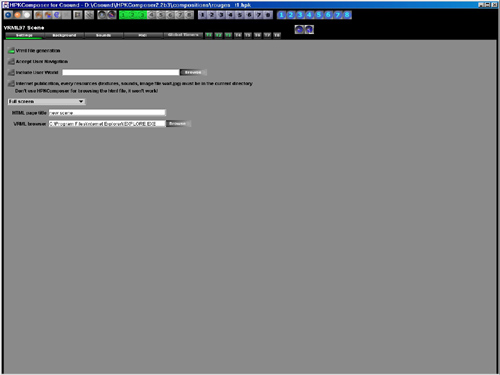
This view lets you navigate through the tabbed panes, and launch the VRML browser, or the program that makes possible the MIDI interactions with the VRML objects.
Settings
Here you:
- select or unselect the generation of the VRML file
- have the capability to include an external VRML file (see below for the limitations)
- choose the size of the screen and the ratio for the VRML view
- give a title to the HTML page
- and specify the location of the browser you want to use.
Background
The combo box at the top left of the view lets choose the background template for the VRML97 world. A background template defines graphical elements that won't be modified by note events evolutions, or by MIDI interactions, but can be animated on their own. Typically, a template will define background colors for the world, fog, camera evolutions, ambient light and other attributes. Three templates are provided:
- Moving texture, a four points polygon with a texture moving as the camera moves is displayed at the center of the scene
- Animated Textures, four polygons (four points) are displayed at the center of the scene. Each polygon has a texture that changes overtime.
- Landscape, basic background attributes.
The background can be changed independantly from other settings.
Sounds
This panel lets control how the sounds generated by Csound will be set in the VRML world. There are two modes:
- Unique ambient sound, a unique sound file is generated from the activated Structures and is placed in the 3D world.
- Multiple sounds, a sound file is generated for each activated Structure, and are placed in the 3D world at different locations (or the same). The follow option ties together the sound and a graphical object. In this case, the sound will move as the graphical object moves. It is also possible to control the volume of the sound from an external MIDI device (by using a specific program HPKMidiVrml).
Sounds are spatialised, if the camera moves or if the user navigates in the world, the sound will move in the stereo space according to its position and those of the user. The minBack, minFront, maxBack and maxFront defines the inner ellipsoid for the sound. Here is a figure coming from the VRML97 specification
The Sound node has an inner ellipsoid that defines a volume of space in which the maximum level of the sound is audible. Within this ellipsoid, the normalized sample data is scaled by the intensity field and there is no attenuation. The inner ellipsoid is defined by extending the direction vector through the location. The minBack and minFront fields specify distances behind and in front of the location along the direction vector respectively. The inner ellipsoid has one of its foci at location (the second focus is implicit) and intersects the direction vector at minBack and minFront.
The Sound node has an outer ellipsoid that defines a volume of space that bounds the audibility of the sound. No sound can be heard outside of this outer ellipsoid. The outer ellipsoid is defined by extending the direction vector through the location. The maxBack and maxFront fields specify distances behind and in front of the location along the direction vector respectively. The outer ellipsoid has one of its foci at location (the second focus is implicit) and intersects the direction vector at maxBack and maxFront.
The minFront, maxFront, minBack, and maxBack fields are defined in local coordinates, and shall be >= 0.0. The minBack field shall be <= maxBack, and minFront shall be <= maxFront. The ellipsoid parameters are specified in the local coordinate system but the ellipsoids' geometry is affected by ancestors' transformations.
MIDI
MIDI interactions are available through the use of a specific stand alone program HPKMidiVrml, available for the Windows environment only, as it is using the Cosmo player COM interface. This program traps MIDI information on the MIDI in device, sends information to the VRML run time through the COM interface, and also sends MIDI information to the MIDI out device. The MIDI interaction settings view allow to customize the routing of MIDI in messages to the MIDI out. There are four programs available for live interactions. Each program is activated by a specfic MIDI Program Change message, and defines four layers for MIDI output or VRML object parameter control. The MIDI note messages will be re-routing to the MIDI out base on these layers, and the VRML world will receive also these informations (note value, velocicty and layer) for graphical object transformation.
Transforms
A transform node is a group of up to 16 Graphical
Objects. Graphical objects are
representing by the following view in the
Transform page ![]() . You can activate/deasctivate a Transform
or a graphical object, desactivation means
that it is not generated in the VRML97 file,
but every property is kept. The Combo Box
lets choose the Graphical Object type and
the parameters button lets edit its atributes
and the relationships with Structure definitions.
. You can activate/deasctivate a Transform
or a graphical object, desactivation means
that it is not generated in the VRML97 file,
but every property is kept. The Combo Box
lets choose the Graphical Object type and
the parameters button lets edit its atributes
and the relationships with Structure definitions.
A typical Graphical Object attribute user interface is like this
![]()
On the left, you find the default value for the attribute, then a switch button that lets assign an interpolator to this attribute: the attibute may now evolve in time. The Combo box precises how this evolution is controlled: either by a user interpolator, either by an interpolator following a note event paramater, or by MIDI input messages. By clicking on the button on the right, a view is displayed for editing the interpolator parameters.
The interpolator follows the Structure
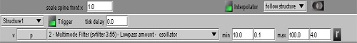
The combox box on the left assign a Structure to this interpolator. For each note event generated by the Structure, a discrete value will be calculated for the Graphical Object parameters. The tick delay parameter is usefull when the sound has a slow enveloppe: it helps to synchronize the Graphical Object discrete value to the sound event by delaying it, The trigger checkbox forces Graphical Object discrete value to the default beetwen two note events. The transitions are smooth without triggering, and percusive like with it.
Then you find the different fields of the
Graphical Object attribute. You can decide
if a field follow the Structure or not, what
note event parameter will be used as a source,
and what are the values for the minimum and
maximum note event parameter, as well as
their conversion in the VRML world. By clicking
on the "r" button, the min and
max values are set according to the existing
values in the Structure (this is a rough
estimate, not exactly accurate, look at the
values in the Structure Graphical view for
the exact minimum and maximum values).
You can choose not to use the min/max values
as found in the Structure. This is interesting
when the note event density is high, thus
giving a too fast visual evolution. In this
case it is possible by setting the minimum
and maximum values to take only the note
event parameters that are in some range.
This will limit the too fast changing visual
effect.
Tips
Transparency attribute is in the range 0 (visible) to 1(transparent).
The generated VRML file is not suitable for web browsing. Textures and sounds location must be edited before sending the VRML file on your web server.
A HPKComposer composition received from someone else of from the distribution package must be edited for changing the locations of textures and sound objects.
The VRML file that you may include in the generated one must follow the following convention: it must be a file with one top node that is a Transform. If you are using a VRML editor, you have to check the contant of the file and to clean it. Example:
#VRML V2.0 utf8

Transform {
  children [
    Shape {
      appearance  Appearance {
        material Material {
                   diffuseColor 1 0 1
        }
      }
     geometry Extrusion {
        solid FALSE
        creaseAngle      3
        crossSection [ 0 150, 59 140, 108 108, 140 59, 150 0, 140 -59, 108 -108, 59 -140, 0 -150, -59 -140, -108 -108,
         -140 -59, -150 0, -140 59, -108 108, -59 140, 0 150 ]
        beginCap FALSE
        endCap TRUE
        orientation [ 0 0 1 0 ]
        scale [  1.0  0.1,  0.01  0.01 ]
        spine [ 0 0 0, 0 0 -300 ]
      }
    }
  ]
}